


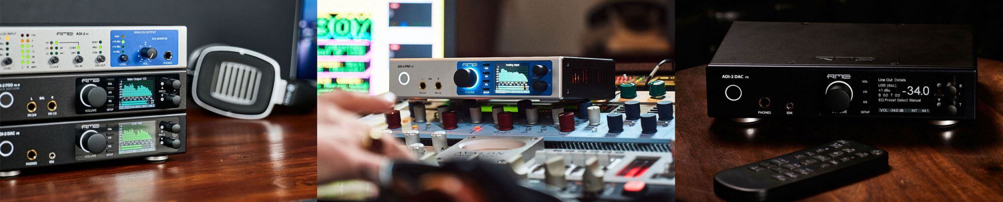
- Totalmix FX
- TotalMix Remote
- DIGICheck
- SteadyClock
- SteadyClock FS
- SyncCheck
- SyncAlign
- Intelligent Clock Control
- MADI Setup Examples

TotalMix FX
(this text is an excerpt from the RME Fireface UFX manual, channel counts and effects may vary on your device)
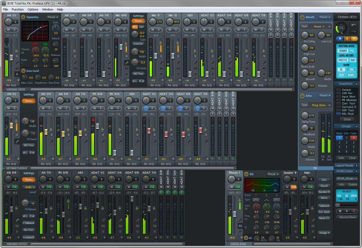
The DSP-based TotalMix mixer allows fully independent routing and mixing of all 30 input and playback channels to all 30 physical outputs. Up to 15 totally independent stereo submixes plus a comprehensive Control Room section offer unrivalled monitoring capabilities and unsurpassed routing flexibility.
And there is more: The next generation of TotalMix delivers hardware mixing/routing with lots of new features and a highly improved usability. For a seamless integration of the new features TotalMix FX has been rewritten from the ground up.
Every input and output channel comes with a luxury feature set, comparable to a full-scale digital console. The effects per channel include 3-band parametric EQ, adjustable Low Cut, Auto Level, Compressor, Expander, MS Processing and phase reversal. The Reverb and Echo effects unit is available for all channels by a stereo send and return bus. The UFX easily surpasses the competition by offering all these effects even at 192 kHz operation.
Two DSPs ensure an impressive performance even in extreme applications. As usual with RME, TotalMix is available with all channels (90) at all sample rates, completely unlimited. The second DSP calculates the effects only, therefore has sufficient resources. For example, at 48 kHz 60 EQs, 34 Low Cuts and Echo can be activated. With activated Reverb and Echo still 46 EQs and 32 Low Cuts are available.
The FX-DSP uses automatic overload surveillance. As soon as no effect can be added anymore the TotalMix surface will clearly signal this condition. When changing to higher sample rates the UFX automatically deactivates all effects that exceed the DSP's performance - the DSP will never be overloaded. This also prevents the user from destroyed loudspeakers.
The complete effects section not only adds a lot of flexibility to the recording chain, but makes latency burdened software dispensable. TotalMix can easily replace any external mixer, e.g. to create different latency-free monitoring mixes with EQ and Reverb for the main studio monitors and the headphone of the vocalist(s) in the recording room.
Furthermore the DSP hardware calculates RMS and Peak levels for all 90 level meters, so there is zero CPU load on the host.
The main functions of TotalMix can be remote controlled via MIDI with any Mackie Control compatible controller.
TotalMix FX Tutorials
|
RME TotalMix FX Tutorial Part 1 |
RME TotalMix FX Tutorial Part 2 |
Features/Differences to classic TotalMix: |
|
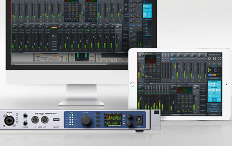 Wireless control with TotalMix Remote
TotalMix Remote is a free companion app for TotalMix FX that allows you to control your RME interface over network, giving you the option to monitor and mix from a different computer to the one your interface is connected to, including over Wi-Fi.
You can even use an Apple iPad, for wireless touch-screen control when you’re playing a venue or working in the studio.
TotalMix FX Remote – Quick Start Guide
1 – Download and install TotalMix Remote on the Remote computer (or iPad) you want to control your interface from.
2 – On the Host computer (the one which your interface is connected to), open TotalMix FX and select Options from the program’s file menu, then select Network Remote Settings (on a Mac), or Host Connection Settings on Windows. This window will also provide you with the Host computer’s IP address.
3 – Check that the Enable TotalMix Remote Server box is ticked. On Windows, you will also see a Firewall warning – make sure you allow TotalMix Remote.
4 – Make sure that both the Host and Remote computers / iPad are on the same network, then open TotalMix Remote*. A dialog box should open automatically (for entering the IP address and port number), but if it doesn’t you can also click on the Search Connected Hosts option.
*On an iPad, tap on the gear symbol in the upper right corner, then on Host Connection Settings.
5 – In the resulting dialog box, type in the Host computer’s IP address (e.g. 192.168.0.101), and make sure that Activate is ticked. The port will usually default to 7009 (and should be left as this), however if the port is occupied for some reason an error message will show, in which case simply choose a different port. This will bring up an additional Firewall warning – again, allow TotalMix Remote to enable it.
6 – Click Done or OK, and TotalMix Remote will open within a few seconds. You are now free to control your audio interface from your Remote computer or iPad!
Downloads
TotalMix Remote for Windows
http://www.rme-audio.de/download/tmfx_win_remote.zip
TotalMix Remote for Mac
http://www.rme-audio.de/download/tmfx_mac_remote.zip
TotalMix Remote for iPad
https://itunes.apple.com/us/app/totalmix-remote-for-ipad/id1345471593?mt=8
DIGICheck for Mac and Windows
https://www.rme-audio.de/downloads.html
DIGICheck
Test, Measurement and Analysis Tool for RME Interfaces
RME interfaces not only provide you with a professional digital audio interface, but also with a unique software tool: DIGICheck, the incredible utility for test, measurement and analysis of the digital audio data stream.
This TECH INFO describes the functions and the technology used in DIGICheck. Please be aware that DIGICheck works with Windows and Mac OS X, but only with hardware from RME. This is due to special implementations within the hardware, that aren't available with any other card. RME interfaces are based on RME's own chip design (realized in a FPGA). Because of this you won't find any other card in the market that gives you a Channel Status display, a 100% accurate 24-Bit level meter, a decoding of the CD-subcode, and hardware based RMS calculations.
A description of DIGICheck's latest additions, Totalyser, Spectral Analyser and Vector Audio Scope, can be found here.
Click here to go to RME's website and download the latest version of DIGICheck
Technical background: the 32 bit technology
To our knowledge, RME's DIGI96 series was the first audio card ever to allow the recording of the complete 32 bit digital audio data stream. Besides the usual 24 audio bits P, C, U and V bits are also transmitted. That's only 28? Right, the first 4 bits form the preamble. This synchronization signal isn't needed anymore after a successful receiving and decoding of the signal. To use the data of the PCUV-bits, the start of the block must be known. Therefore the data stream sent to the record program also includes the CBL (channel block start) signal since the introduction of the DIGI96 series.
A detailed description of the used transfer format can be found in the TECH INFO Track Marker Support.
The Software DIGICheck
The software is very easy to use, well designed, useful, and includes many valuable options. A detailed online help and technical reference is also included.
After the first start the program asks for the 'Record Device' (data source) and the kind of font and size for screen presentation. Both can be configured at a later time too. A small display with a good overview is achieved using Arial 8, else Arial 10 is recommended. These and all other settings are stored in Windows' registry.
In the beginning DIGICheck worked like any other record software, opening one or multiple devices for recording, but not writing the incoming data to disk. Therefore DIGICheck only worked as long as no other record program used the selected devices.
Since Hammerfall and Hammerfall DSP, DIGICheck uses the multiclient drivers of the interface to access record and playback (!) data. This happens competely in the background, in parallel to any (!) currently active audio software.
Each function allows to optimize and store the size and position of its window. The configuration of the Level Meters is done via F2 or a menu entry. The Channel Status Display may be printed, 'Deactivate Screensaver' and 'Always on top' sure don't need to be explained.
The Functions in DIGICheck
Level Meter
This function provides highly precise level meters with 24-Bit resolution. All parameters like range, resolution and color are completely configurable without limitations in 'Level Meter Setup'. Because of the highly configurable parameters the Level Meter is ready for a great number of applications:
- Peak level measurement
- RMS level measurement
- Over detection
- Measurement of the correlation (phase)
- Measurement of dynamic and signal to noise ratios
- Display of the difference between RMS and Peak (volume)
- Long term peak detection
The peak level (AC+DC) is shown in the inner bars. Every single sample is used for computing Peak level and RMS level. A single sample is sufficient for a 0 dBFS readout. Overs are indicated when more than a user defined count (1 to 20) of consecutive full scale samples occur. A Peak Hold function with adjustable hold time (0.2 s to 100 s) is also implemented.
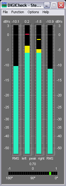
The RMS level (only AC) is shown in the outer bars. The reference (0 dBFS) is a sine with digital full scale level. This allows easy comparisons of RMS and Peak with usual signals. The RMS display is based on a mathematical true calculation of the root mean square, and will therefore display highly (!) accurate values.
For example: Play back the file crest_16.wav (found on our download page or on the RME Driver-CD) using the DIGI96, connect output to input (Clock Mode Master!) and start the Level Meter. It shows a peak value of 0 dBFS, but a RMS-value of only -16,1 dBFS. Every measurement device based on usual analog RMS detectors will come in big trouble confronted with such a high Crest value (ratio peak to rms) and will show wrong values around -6 dB.
Thanks to 24-Bit the meters break down the lower barrier. Finally you are enabled to see the real dynamics of your equipment! And we don't make jokes: The RMS levels shown from DIGICheck equal exact (!) the values measured by 10.000$ audio measurement systems! To be more specific they equal RMS unweighted, which means RMS without any special weighting filter. To achieve a better readability at lower noise levels we recommend to set the release rate to 10 dB/s (or to use the Bit Statistic instead, see below).
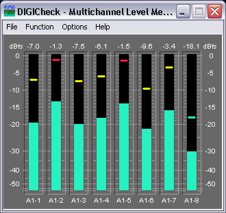
Multichannel Level Meter
Besides the 2-Channel level display also an 8-Channel level display is available. This Multichannel Level Meter uses the same settings options as the 2-Channel Level Meter. The bar can be set to display RMS or Peak.
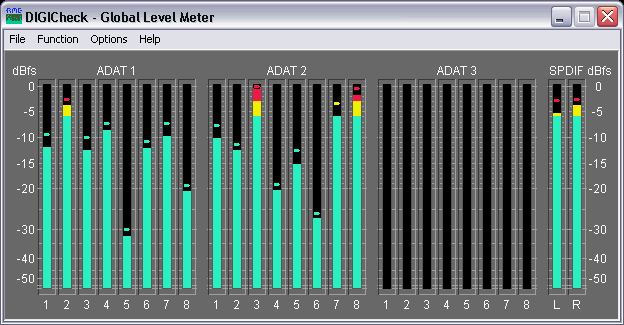
Global Level Meter
DIGICheck's Global Level Meter displays all available channels of the the interface simultaneously. This function is mainly intended as fast overview of current configuration and input signals. Channels with invalid input signals will be greyed out.
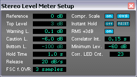
Level Meter Setup
The visible display range can be set between 0 and -160 dBFS. The measurement includes the whole range available from the received audio bit resolution, displayed in 0.1 dB steps. The change in color is defined in 'Warning Level'. Set to 0 dB a color change is only performed on the highest peak hold step - when 'Over' is detected. The number of consecutive full scale samples for an 'Over' indication can be defined between 1 and 20. As the display of a phase relationship makes no sense below a certain threshold the correlator's display will be turned off. The number of LEDs in the Correlation Meter is also configurable in a wide range.
Channel Status Display / User bits
This function decodes and displays the channel status information contained in the SPDIF signal. In addition the real sample rate is measured with an accuracy of ± 100 Hz. A printing function provides a hardcopy of the channel status.
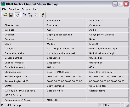
Even if you're not a super-duper technician you can gain useful information from this table. Incompatibilities among digital devices are explained by a set 'Emphasis' or an active copy protection (field 'SCMS'.) No sound from the CD-player? Perhaps the CD is full of scratches, showing 'Data Invalid' (resulting in an automatic mute of the DA-converter.)
When connecting a CD-player or a DAT-recorder parts of the subcode (coded into the user bits) will be shown in the 'Validity-Bit' field. The name changes to 'Validity-Bit/CD-Subcode' or 'Validity-Bit/DAT-Subcode' and shows track number, index and current play time. From the DAT's subcode the Start-ID (not track number!) is presented whenever one occurs. Of course ALL information in the subcode may be decoded thanks to the 32 bit mode of the DIGI96 series, but this is only an example. A professional hard disk recording software might use this information when transferring a 2 hour DAT tape into the PC to automatically set markers at the begin of each track (at each Start-ID.)
Bit Statistic & Noise
This function shows the state of the audio bits. Three states are detected: always low (0), alternating and always high (1.) Alternating means the bit is in use, zero indicates unused bits and permanent one is often caused by a defective AD-converter.
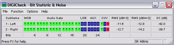
The Bit Statistics allows to determine the real resolution or word length of audio signals, for example at the output of A/D-converters, mixing desks and effects devices. Audio data will be indicated green (normal, bit used), otherwise blue (permanent 0, bit not used). In case of permanent 1 (error or DC) the colour changes to red. The normal state of the Channel Status bit and the Validity bit is green, permanent values (red) indicate an error or distorted audio data.
Glossary
Crest value: Ratio between peak and RMS value. Music with small crest value is louder than one with a high crest value.
dBFS: deci Bel Full Scale. Logarithmic level ratio referenced to digital full level (7FFFH / 8000H).
RMS unweighted: Root Mean Square measurement without special weighting filter, measures flat within 22 Hz to 22 kHz.
Sample frequency: Number of samples taken from the analog signal per second.
Word length: Same as bit resolution. Number of bits per sample. 16-Bit: 65536 steps or 96 dB dynamic range.
SteadyClock (TM)
Theory
Usually a clock section consists of an analogue PLL for external synchronisation and several quartz oscillators for internal synchronisation. SteadyClock requires only one quartz, using a frequency not equalling digital audio, therefore effectively avoiding disturbances. Latest circuit designs like hi-speed digital synthesizer operating at unsurpassed 200 MHz, a fully digital PLL design, and efficient analogue filtering allow RME to realise a completely newly developed clock technology, right within the FPGA, at lowest costs. The clock's performance exceeds even professional expectations. Despite its remarkable features, SteadyClock reacts quite fast compared to other techniques. It locks in fractions of a second to the input signal, follows even extreme varipitch changes with phase accuracy, and locks directly within a range of 28 kHz up to 200 kHz.
Compared to other technologies, one of SteadyClock's main advantages is its single stage design. Usually the PLL consists of a first stage reacting as broad clock locking circuit, then a second stage acts as narrow locking circuit. Only the narrow circuit provides jitter suppression, so that locking takes some time, and in varipitch applications, where the second stage does not get active at all, nearly no jitter suppression is provided. SteadyClock locks directly and provides high jitter suppression throughout!
Measurements
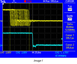
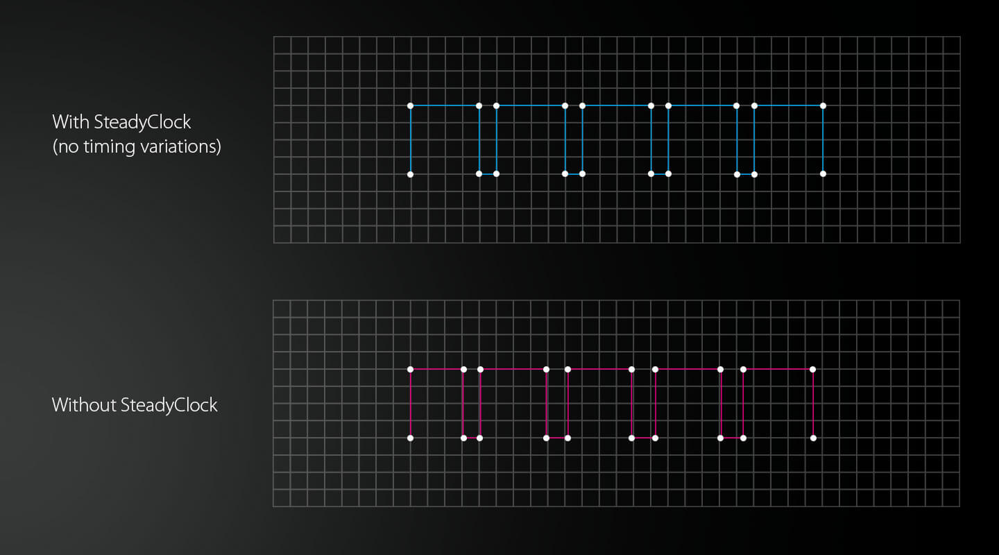
SteadyClock has originally been developed to gain a stable and clean clock from the heavily jittery MADI data signal. The embedded MADI clock suffers from about 80ns jitter, caused by the time resolution of 125 MHz within the format. Common jitter values for other devices are 5 ns, while a very good clock will have less than 2ns.
Image 1 (below) shows the MADI input signal with 80ns of jitter (top graph, yellow). Thanks to SteadyClock this signal turns into a clock with less than 2ns jitter (lower graph, blue)
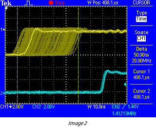
Using other input sources like AES, SPDIF, word clock or ADAT, one most probably never experiences such high jitter values. But SteadyClock is not only ready for them, it would handle them just on the fly.
Image 2 (above) shows an extremely jittery word clock signal of about 50 ns jitter (top graph, yellow). Again SteadyClock provides an extreme clean-up. The filtered clock shows less than 2ns jitter (lower graph, blue)
Real-world Operation
The following example shows SteadyClock's behaviour in real-world operation. The ADAT input of the HDSP 9632 uses an advanced Bitclock PLL. But this PLL does not provide any jitter suppression within the audio range. Therefore the quality of the clock extracted from the ADAT signal depends on the specific ADAT source.
But on the HDSP 9632 (also ADI-648 and HDSP MADI), SteadyClock will process the ADAT clock signal after its extraction.
Image 3 (below) shows the word clock output of the HDSP 9632, which is directly fed from the internal master clock - and with this from SteadyClock.
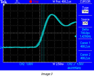

In this case the card is set to AutoSync, and receives an ADAT signal with very low jitter (below 1 ns). The remaining jitter behind BitClock PLL and SteadyClock is hard to detect at all, with a value of around 700 ps (0.7 ns).
Image 4 (above) shows the same situation with an ADAT signal of about 40 ns of jitter. The input jitter is nearly completely removed, the output of the HDSP 9632 again shows around 700 ps (0.7ns).
The signal processed by SteadyClock is used internally to clock on-board AD- and DA-converters, and to clock the digital outputs. Additionally it is available directly at the word clock outputs.
Measurement using Audio Precision System Two
We tested SteadyClock using an Audio Precision System Two audio test system. The AP was connected to an ADI-4 DD, as the AP can measure jitter only on AES inputs and outputs. SteadyClock is used in the ADI-648, ADI2, HDSP MADI, HDSP 9632 and Fireface 800. The measurement results are valid for all the mentioned units as well.
The AP generated an AES signal which had been modulated with 10ns, 20ns, 50ns and 100ns jitter. The jitter frequency was not fixed, but changed in 401 steps between 20 Hz and 100 kHz. This way, a diagram was generated which shows the remaining jitter related to the jitter frequency, or in other words the amount of jitter reduction relative to the jitter frequency.
Doing a loopback selftest, we found that the AP only measures exactly within the range 50 Hz to 50 kHz, so we limited the test results to this range.
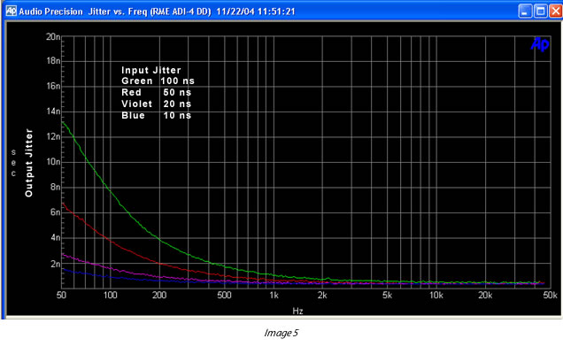
Image 5 (above) shows that even outside the expected filter range, SteadyClock heavily reduces jitter. An input jitter of 100 ns modulated by 50 Hz is brought down to 14 ns, at 100 Hz it is only 7.5 ns. Already at 500 Hz the remaining jitter is always below 2 ns, and looking at more real-world values like a 10 ns input jitter, the output jitter stays below 1 ns nearly all the time! Also the advertised value of 30 dB reduction at 2.4 kHz turns out to be an even better 'more than 40 dB'!
This measurement shows that SteadyClock can not only compete with other known jitter reduction techniques, but in fact is able to outperform them easily in several regards, like efficiency, speed, ease of use and costs.
Conclusion
The SteadyClock technology of RME's latest products guarantees an excellent performance in all clock modes. Its highly efficient jitter suppression enables ADI-648, HDSP 9632, HDSP MADI, ADI-2, ADI-4 DD and Fireface 800 to refresh and clean up any clock signal, and to provide the clock signal as reference clock at the word clock output. At the same time, analogue conversion is performed on a guaranteed level of highest quality, completely independent from the kind and quality of the used reference clock. The cleaned and jitter-freed clock signal can be used as reference clock in any application. And the quality of the external (input) clock doesn't matter anymore.
Copyright © Matthias Carstens. All entries in this Tech Info paper have been thoroughly checked, however no guarantee for correctness can be given. RME cannot be held responsible for any misleading or incorrect information provided throughout this manual. Lending or copying any part or the complete document or its contents is only possible with the written permission from RME.
Excellent Performance, Redefined.
About Jitter
In digital audio, the clock frequency is an essential factor, as it creates the correlation between the audio bits and the time reference. Unfortunately, the clock frequency is not always as stable as desired.
Small fluctuations of the clock frequency are referred to as "jitter", measured in nanoseconds (ns). They are the natural-born enemy of any digital audio transfer. The effects of jitter on the audio signal are many - from a somewhat rough sound quality to diminished treble localisation to clicks and dropouts in extreme cases.
To solve these issues, RME have developed a completely new technology for synchronization and jitter suppression in digital audio signals - SteadyClock.
The Evolution of SteadyClock
SteadyClock has originally been developed to gain a stable and clean clock from the heavily jittery MADI data signal.The embedded MADI clock suffers from about 80 ns jitter, caused by the time resolution of 125 MHz within the format.
Common jitter values are 5 ns, while a very good clock source will have less than 2 ns. Using other input sources like AES, SPDIF, word clock or ADAT, one most probably never experiences such high jitter values.
But SteadyClock is not only ready for them, it would handle them just on the fly. SteadyClock reacts quite fast compared to other techniques. It locks in fractions of a second to the input signal, follows even extreme varipitch changes with phase accuracy, and locks directly within a range of 28 kHz up to 200 kHz.
The SteadyClock technology of RME's latest products guarantees an excellent performance in all clock modes. Its highly efficient jitter suppression refreshes and cleans up any clock signal, and provides the clock signal as a reference clock at the word clock output.
At the same time, analogue conversion is performed with a guaranteed level of the highest quality, completely independent from the type and quality of the reference clock.
The cleaned and jitter-freed clock signal can be used as a reference clock in any application. And the quality of the external (input) clock doesn't matter anymore.
SteadyClock FS - Excellent performance, redefined
Today SteadyClock is still the same, with a few small improvements in the latest FS version, like even more efficient filtering, and a design based on a super low jitter reference clock.
The ADI-2 DAC was the first device in RME's range with SteadyClock FS. There is not much to improve with SteadyClock, it has earned its accolades over years of flawless operation in numerous RME devices, guaranteeing that using the internal clock will produce exactly the same sound as when using an external one.
SteadyClock highly rejects jitter and handles all digital interface formats in an exemplary way.
RME Audio ADI-2 Series, High-end Format converter
With SteadyClock FS the focus was put on reducing the self jitter of SteadyClock to new lows, by improving its second, analog PLL circuit, and referencing both Direct Digital Synthesis and PLL to a low phase noise quartz crystal.
The self jitter measured through DA conversion now reaches levels that usually are only available in master quartz clock mode, while SteadyClock still always runs in PLL mode - no matter if internal or external clock, sound is exactly the same (again).
The low phase noise oscillator driving the updated circuit reaches jitter specs lower than a picosecond (ps), an area called FemtoSecond. Hence SteadyClock FS.
Pristine signal conversion, with jitter measured much lower than nanoseconds (ns) or picoseconds (ps), in an area called femtoseconds (fs).
Full Range Capture without compromises
RME Audio has always been completely focused on performance, the company's products are the first choice of audio professionals around the world. Precise German engineering and a relentless pursuit of sonic perfection will ensure the highest quality results — no matter what the application.
 Capture every Detail & Hear your mix as it is
RME's mic preamps and converters are designed to capture every nuance of a performance, with no added sweeteners. Every detail is captured, and nothing is lost.
Neutral conversion allows you to hear the performance exactly as it is in the room — giving you the confidence you need that what you hear in the control room will translate to the final product.
Digital format conversion in RME products are done without any loss or degradation, and SteadyClock FS ensures your sonic image will never experience degradation.
In today's music creating environment, users should never have to tolerate sub-standard reliability and performance — whether the goal is to capture a multi-piece orchestra in a commercial recording environment, tracking a world-class halftime show or a demo in a bedroom studio.
RME Audio products are used daily by working professionals in a wide range of different areas. From recording studios to major broadcast companies, high profile live tours and west end theatre productions, to scientific research establishments and national art installations. You can even find RME products in systems monitoring whale movements near off-shore oil rigs!
Whether you're in the studio, in the desert, out at sea or at home; you can count on your RME Audio equipment to deliver the quality and reliability you need.
SyncCheck
When working with several digital sources it is not only necessary that these are all properly locked, they also have to be totally synchronized. Else drop outs and crackling occurs.
RME's exclusive SyncCheck checks all input signals. In clock mode Master the synchronous operation to the internal clock is checked. This outstanding and unique technology helps to find errors immediately. The actual state of each input is displayed in the settings dialog.
SyncAlign
SyncAlign includes several methods and techniques to guarantee absolute data alignment with regard to time and channels. No RME digital audio card will ever swap channels, not in stereo nor in multi channel mode, regardless what you do with the card and the signals it gets. SyncAlign also controls the timing among the channels, no matter how much are used, they will always start sample-aligned.
When the record while play mode is activated, the corresponding software first starts record and then playback (or playback then record.) SyncAlign can compensate the time difference so that an exact simultaneous start of record and playback in the record while play mode is guaranteed. In asynchronous mode (different programs use different stereo devices of one card) this part of SyncAlign is automatically deactivated.
Intelligent Clock Control (ICC)
Our unique SyncCheck and AutoSync technology has evolved into the new Intelligent Clock Control of the Hammerfall DSP system. HDSP is the only digital I/O-system worldwide capable of measuring and displaying the frequency of all clock sources. Even word clock! Based on validity and current sample rate the system then decides which clock source should be used - fully automated and performed in hardware! With this the HDSP system offers the most easiest handling of the present clocks, although having a lot digital inputs, plus the most advanced support when configuring the clock setup.